This blog shows how to replace the Bonfiglioli MVF 49 gearbox in a Harken 53 electric winch.
We have serviced both the top section of our Harken winches regularly – both the upper section and the electric motor where we check and swap out the brushes, however in the 10 years we’ve owned Impi, I’ve never ventured to do any service to the gearbox on our electric winch. This has proven to be an expensive learning curve to not be doing the regular preventative maintenance program we always claim to be doing on the boat.
By far and away, preventative maintenance to most components of the boat have resulted in relatively trouble free sailing over the oceans. Neglecting to apply this to our Harken Winch gearbox taught me how I need to be on top of the game and certainly check out the other winch gearboxes before they pack up too.
Prior to the winch packing up we felt it was starting to slip – it would grip and then lose it. This would then require us to use manual mode.
Time to remove the gearbox of the main sheet electric winch:
On our Lagoon 440 one needs to remove a roof panel under the winch which exposes the gearbox.
Harken 53 electric winch
Remove the centre bolt using a large flat screwdriver.
A few wraps with the sheet around the winch holds it in place so one can turn it loose
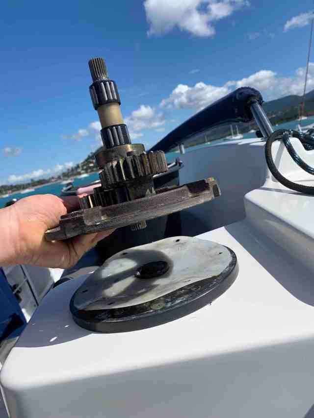
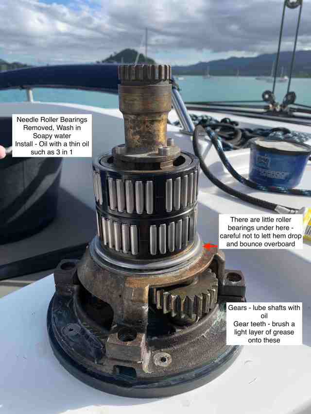
Carefully remove the winch being mindful that some bearings could drop out so have a bucket or container ready and be careful not to lose any parts overboard.
Remove the bolts that hold the assembly to the planetary gear frame.
Carefully lift the assembly off the planetary gear frame being careful not to lose any pieces overboard.
Remove the bolts that hold the planetary gear frame to the base plate.
Lift off the planetary gear frame.
If any of these bolts do not come loose and the tool slips in the head, it may be necessary to use a drill wide enough to drill out the head section to the thread shank.
Once you have lifted the frame off the base plate you can use a vicegrip tool to tightly clamp the shaft and rotate it free.
Remove the teflon plastic disc (there to prevent corrosion to the base plate which is smeared with grease on the underside).
CAUTION:
Make sure the gearbox is tied so it cannot drop or have someone underneath support the gearbox otherwise it will drop once these screws are loosened.
Remove the 4 bolts that hold the gearbox to the frame.
Remove the gearbox from the underside of the base plate. This is done simultaneously to the person above releasing the bolts that secure it.
If you are alone doing this procedure, make sure to tie off the box so it can’t fall and be sure the centre shaft does not fall out.
Tap out the split lock pin with a stump ended punch or similar to slide the pin across.
Use a large screw driver to unscrew the bolt holding the shaft.
By the way – this shaft may be easily extracted ahead of removing the bolt in the previous photo – however, more than likely as was with ours, it could require a press to remove it.
This section to follow is more for interest sake – to show what we discovered in our gearbox, and why we opted for a new one instead of servicing this one.
After removing the collar (4 nuts on studs) remove the top cover.
Tap lightly around the cover with a hammer and then use a large screw driver to pry the lid open. Be careful not to damage any ‘faces’ – in the event of needing to use the unit again one wants to be sure the mating surfaces will seal properly.
Not good !
This should be filled with oil.
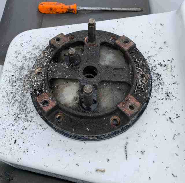
Remove the back / bottom plate.
The teeth on the bevel gear are stripped – time for a NEW REPLACEMENT GEARBOX as a new gear plus all other parts required to put this one together again will not be cost effective against a new unit.
One of the things the supplier may ask you, is what gear ratio your box is:
You can find the model number and ratio here:
Our box is a :
Bonfiglioli
VF 49 P
Ratio: 1:24
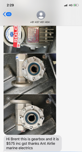
The supplier in the Whitsundays (Thanks for the reference to my mate Mark Rolle) where we were visiting sent me confirmation of what he had in stock as follows – it is the gearbox we purchased:
TIME TO ASSEMBLE EVERYTHING:
The new box comes without some parts, such as the studs and collar, the shaft and bottom cover which one needs to carry across from the failed part.
4 Studs need to be removed.
One can do this by placing two nuts on the stud and locking them together.
In a locked position I can use one wrench spanner on the lower nut and turn the stud out of the casing -see below:
Carry the stud across to the new box – I apply a LOW STRENGTH thread lock ‘adhesive’ to the threaded part of the stud that goes into the gearbox similar to below:
This is the shaft I have removed from our old gearbox – it was frozen solid and had to be pressed out which the supplier kindly did for us.
It’s a good time to clean up and prepare the shaft for our new box:
Check to see that it slides nicely into the new gearbox and easily removable.
Apply Tef-Gel to the new shaft and a liberal amount around the keyway will ensure easier removal to the future.
At this point there are a few different ways to continue … I will try in a manner that explains not well for those less mechanically inclined.
Fit the collar to the new box.
I’ve cleaned up the teflon base collar which holds the spring in place. I’ve lubricated the rubber seal surface with rubber silicon / grease.
This shows the various parts that will be assembled to the shaft.
Here is the shaft assembled
I use a large screw driver with good grip handle to secure the bolt screw in place – It’s important to do this before tapping the lock pin back into position.
The bolt screw collet – V section is the seat for the bolt screw head so make sure that faces the correct way – it can be a fiddly to get the collet to sit flat in its correct position – see the grooved out section on the inside to help flip the collet into place.
Top View
I’ve assembled the electric motor to the gearbox (Gear reduction box) – I’ve tied it up to make it easier to lift. Ana will assist me.
At this point please note the shaft will be able to fall out so it’s very IMPORTANT to be aware of that – If the shaft falls out it could injure someone or damage whatever is below it.
Because the gearbox is not painted at the factory and eventually aluminium can deteriorate in a salty environment, I decided to spray the unit with a long term corrosion protection such as Soft Seal or Tectyl.
This bottom cover plate can be pried off using a screw driver. It’s there to stop any water ingress or oil leaks dropping down into the boat. However, this plate can also allow water accumulation to erode the box over time so I’m deciding to leave it off and will place a ‘tray’ into the ceiling panel to catch any spills.
First I clean up the baseplate, makes sure all threaded sections are clean to take the bolts neatly and I smear all with a thin layer of grease or Tef-Gel.
I have a new replacement seal for the base plate and now carry spare seals on the boat.
The seal should not just slip into place. It needs to be pushed in with some force or even tapped into place if necessary. On my unit I was able to push it in with hand pressure and tap the last bit into its final position. The pic above shows how far I was able to push it in by hand. I tapped the last part in.
Lift the gearbox and motor into place (Be sure not to let the shaft drop) – secure the 4 bolts from the top that hold it there.
Place teflon / plastic protection cover over the base plate.
Clean the planetary base plate ready for installation.
Be sure to put TefGel on ALL bolts installed – it will save headaches next time we need to remove them.
This photo is for reference – shows gear position – do not forget the plastic cover that sits between this assembly and the base plate – not present in this photo.
With the planetary assembly on the base plate and having aligned the holes through the plastic cover, bolts in place – tighten the bolts sufficiently enough to secure it in place.
NOTE:
This post is more to do with the gearbox assembly to the winch than servicing or assembling the top section. I’ve included photos of the top section for ease of reference.
Place the carrier assembly over the planetary assembly and secure the bolts.
Insert and tighten bolts to the carrier assembly
Refer to photos at the beginning of this post when stripping for more angles.
Other photo’s that may be of interest for clearer understanding:
This is what the underside looks like with the gearbox removed and top section in place.
The pic below is more for showing how the principle works – the collar is removed – the spring would usually sit on a teflon / plastic base within the collar.
The male spline in Pic 1 marked A is engaged in the female spline marked A1 in Pic 2.
It is kept there under upward spring tension.
The engagement of the splines causes the drive of the electric motor through the gearbox to the winch.
When a winch handle is inserted for manual operation, the shaft marked B in Pic 1 presses onto the lock pin marked B1 in Pic 2 (inside the splined section body) – this causes the splined housing to lower uncoupling the splines A and A1.
This disengages any drive to the gearbox and the winch now turns under manual pressure through the winch handle.
Great post, I will use this when I service my electric winch gearboxes. Question, what about the electric motors for the whiches. Should they be services, brushes replaced, etc? I can’t find any reference material online.
Hi, I’m doing the same at the moment. Fwiw the replacement gearbox from bonfiglioli was just 160 euro. Can you let me know where you got the replacement base seal?
Great post!
Came acros this after disassembling the whinch and figuring that the ‘grinding noise’ comes from the gear box on one of my ST 48.2 Harken….
Regards, Joeri
Hi Brent,
Our 440 (2007) electric winch has just failed here in Martinique. You can imagine how useful your blog post is to me – pure gold. I’ve just removed the access panel outside the saloon door and your pics will show me the way. Thank you.
Hello
amazing write up here. I don’t see anything regarding the oil that is all over under both my winches. Is this inside the new unit and sealed in?
J-
Hi Brent !
Hope you still out there !
Just done the same service on my winches and gearboxes, looking the same as yours
Would you agree that the teflon base collar and the rubber seal are very important to keep water out as well as the seal for the base plate.
The funny thing on my base plate is the seal came out the opposite way you show, what is correct and is there to teflon base collar on top , i have one
Trying to find these seals on Harken part list but very difficult, any tricks ?
Winches 60.2/53.2/48.2 are E and boat First 50 produced in 2006/2007
Happy sailing from S/Y Virtue, home harbour far north in Grimstad, Norway
Rgds
Thor Svendsen
Hi Thor 👋 – my ancestors are from Norway area and our surname starts with Grim – Grimbeek (I think originally Grimbeeck )
Yes you make some good points and the Teflon base is very important and for sure if you could have a Teflon collar ontop of the seal would be good. Regards the seal direction one would almost certainly want the lip facing the direction to keep water out .
As for the seals you can take these to any bearing supplier and he will give you after market seals to match – I do this for bearings too !
Thanks buddy and hope to share an anchorage with you someday 🍻


Great post, I will use this when I service my electric winch gearboxes. Question, what about the electric motors for the whiches. Should they be services, brushes replaced, etc? I can’t find any reference material online.
LikeLike
Hi Ed, the electric motors can be serviced in the same way as the windlass on our page. Let us know how it goes!
LikeLike
Hi, I’m doing the same at the moment. Fwiw the replacement gearbox from bonfiglioli was just 160 euro. Can you let me know where you got the replacement base seal?
Thanks
LikeLike
Hi Joe , are you in Australia?
LikeLike
Hi Joe, Any chance you have the part number for that gearbox handy? I find my self in the unfortunate position where I have to replace two of these.
LikeLike
Great post!
Came acros this after disassembling the whinch and figuring that the ‘grinding noise’ comes from the gear box on one of my ST 48.2 Harken….
Regards, Joeri
LikeLike
Hi Joeri, it was a pleasure to meet you in Tauranga and we hope all is well
LikeLike
Hi Brent,
Our 440 (2007) electric winch has just failed here in Martinique. You can imagine how useful your blog post is to me – pure gold. I’ve just removed the access panel outside the saloon door and your pics will show me the way. Thank you.
LikeLike
Gerry, thanks very much for your comment. Hope all is good now!
LikeLike
amazing article, just the info i needed! thank you
LikeLike
Hello
amazing write up here. I don’t see anything regarding the oil that is all over under both my winches. Is this inside the new unit and sealed in?
J-
LikeLike
Hi Brent !
Hope you still out there !
Just done the same service on my winches and gearboxes, looking the same as yours
Would you agree that the teflon base collar and the rubber seal are very important to keep water out as well as the seal for the base plate.
The funny thing on my base plate is the seal came out the opposite way you show, what is correct and is there to teflon base collar on top , i have one
Trying to find these seals on Harken part list but very difficult, any tricks ?
Winches 60.2/53.2/48.2 are E and boat First 50 produced in 2006/2007
Happy sailing from S/Y Virtue, home harbour far north in Grimstad, Norway
Rgds
Thor Svendsen
LikeLike
Hi Thor 👋 – my ancestors are from Norway area and our surname starts with Grim – Grimbeek (I think originally Grimbeeck )
Yes you make some good points and the Teflon base is very important and for sure if you could have a Teflon collar ontop of the seal would be good. Regards the seal direction one would almost certainly want the lip facing the direction to keep water out .
As for the seals you can take these to any bearing supplier and he will give you after market seals to match – I do this for bearings too !
Thanks buddy and hope to share an anchorage with you someday 🍻
Regards
Brent
LikeLike