
Our Harken winch for our main halyard starting ‘playing up’ and typical of Brent’s style, the minute we find an symptom we immediately work on a cure before we have a total failure.
The symptom was that the winch on a fast setting would tend to ‘chatter’ i.e. it would not have continuous motion and would ‘stutter’ for want of a better word or way of describing it.
After stripping all the components down and making sure there is no obvious mechanical issue with the winch, gearbox or electric motor our attention went to the ‘Harken Control box’ or solenoid .
The solenoid takes its signal from the electric foot switch and causes contact between the high speed or low speed cables that power the winch.
Since we are sailing in remote areas sometimes and parts are hard to come by, Brent has disassembled the solenoid to check if perhaps the ‘contacts’ are not burnet out as this is an issue after time in use with solenoids.
As you can imagine, when two contacts are brought together under load and applying current, the moment of contact and release bringing on electrical current will have a tendency to create an ‘arc’ and this can burn out the ‘contactors’
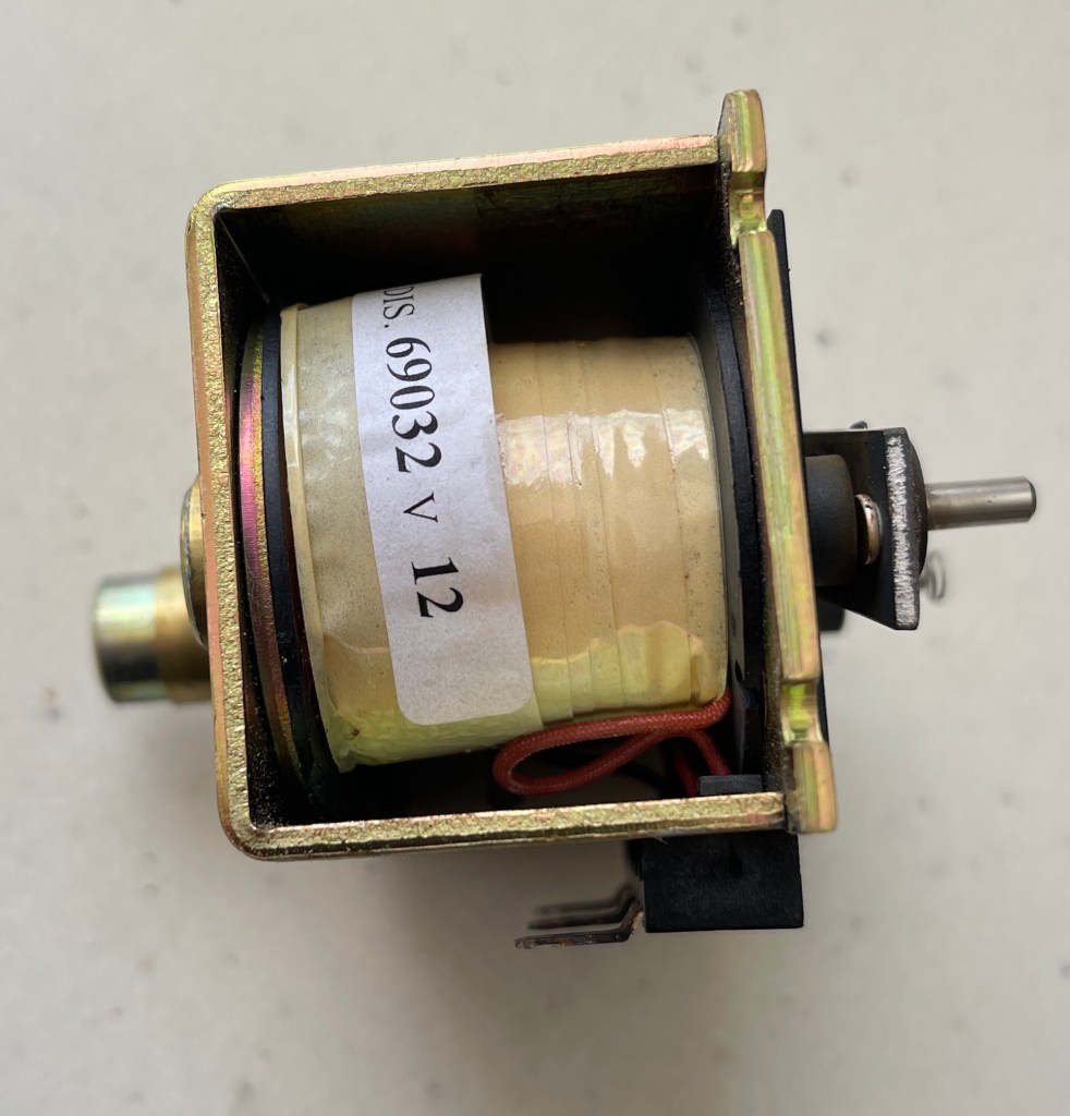
Here is our solenoid
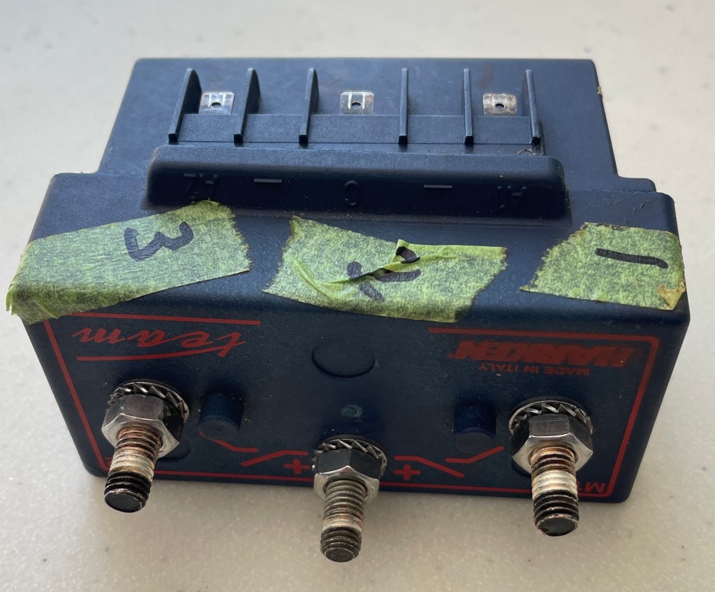
Brent has marked the contact points for the main electrical cables . The middle one is the main POSITIVE CABLE to the battery via the trip switch. No1. is the fast motor speed and No3. is the slow motor speed. The smaller spade style fittings are from the foot switch and provide the command to engage the appropriate speed cables. The middle spade is the negative and goes to the negative post on the electric motor.
Time to open the unit and inspect the internals:

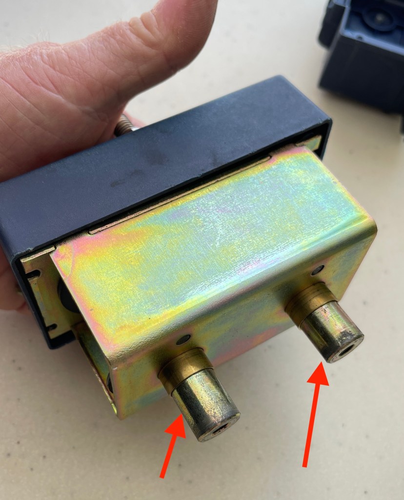
Turn the box over and find 4 screws that hold the upper and lower casings in place. Note: there is a rubber seal gasket that seals the two and should not be damaged
Now we will carefully separate the two sections bearing in mind there are loose parts and springs we do not want to drop and loose

Bottom section removed – It was a good idea to hold the unit upside down for the initial case removal.
Be aware that the items marked by red arrow can slide out
We now want to remove the upper casing section
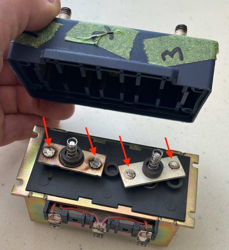
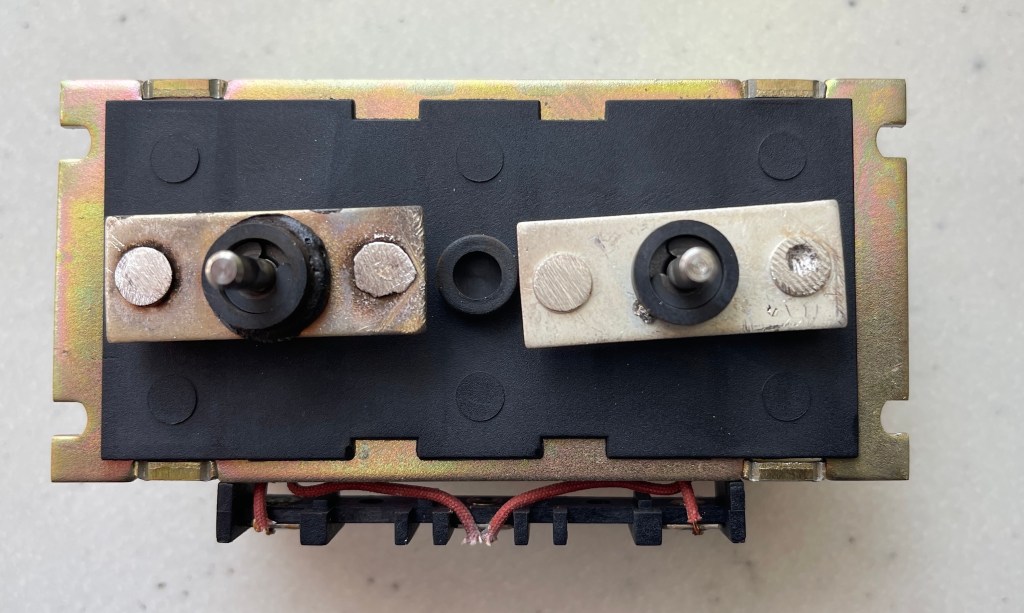
The base is placed on the table so the lower sections do not drop out and exposing the top section we can see the plungers and springs and yes, the contactors are burnt as can be seen above and below (the red arrows) – this is caused as the contacts are brought together and a small ARC occurs

The high speed contactors (terminals) are worse than the slow speed.
Since we are sailing remote we need to make a plan and the only plan we have is to clean up the contact points and use some old spares from a previous replacement we did. Generally the high speed contactors burn out faster than the slow speed contactors so we can utilize the slow speed contactors from a previous replacement to the high speed in this unit.
It would be nice if we could buy this section separately or even replace the contactors as a separate item – perhaps someone smart reading this can tell us if this is possible in the comments section.
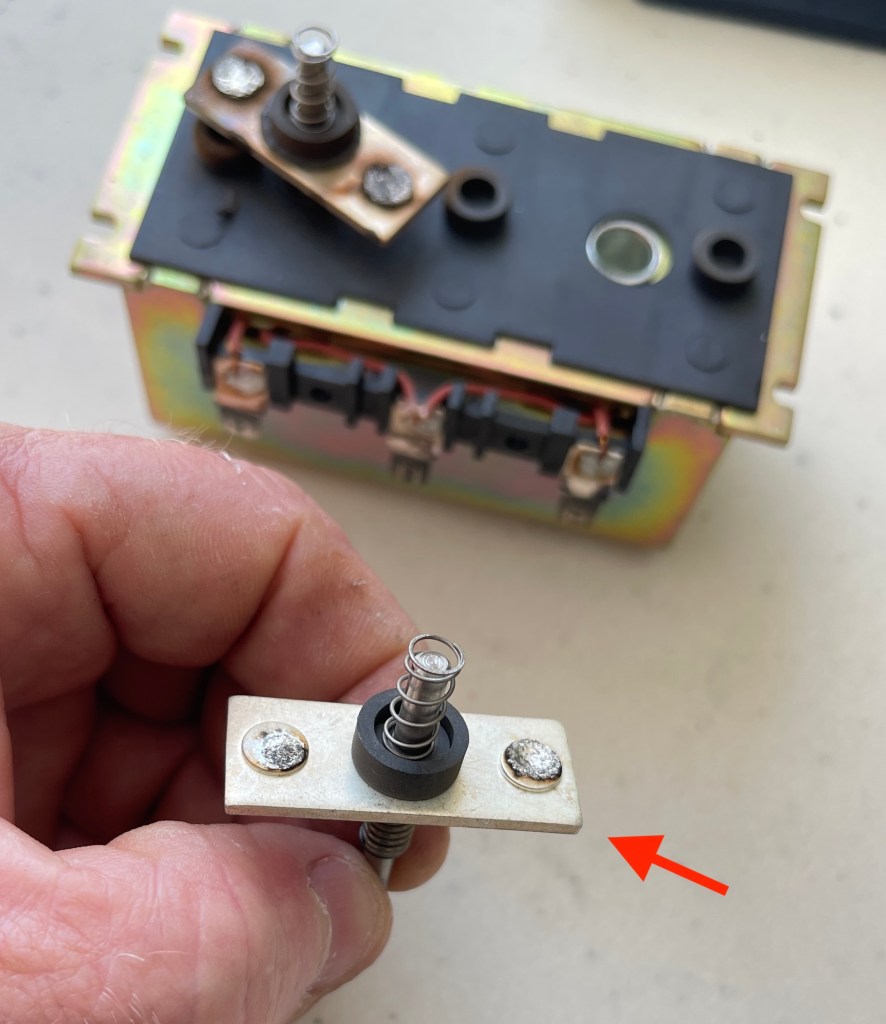
Well where there is one contact section there has to be another and this contact seat sits in the upper case (see below).

The contactors below get raised to make contact above when an electrical field is placed on the coils. The coils magnetize the plungers which are moved upwards against spring tension to make contact with the contact seats in the upper housing. When the foot switch is released the magnetic field is cut and the plunger is pushed away by spring tension. Of course we want to make sure all the components are in good condition and there is no discoloration to the springs as they play a pivotal role in the process.
For interest, the below image shows the ‘COIL’ which when current is applied creates a magnetic field to force the plungers and contactors upwards
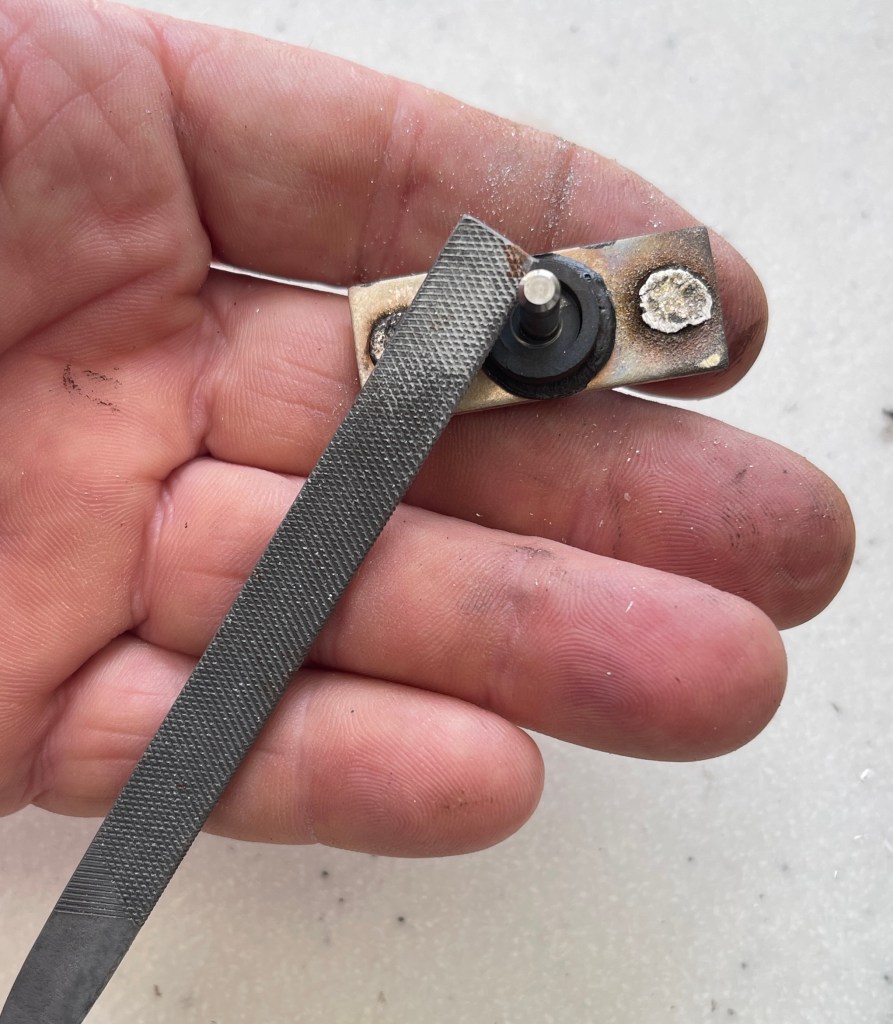
Above, we’ve used a small file to clean the contactors as best we can and until we can find a replacement solenoid. One can use different methods such as ‘scratching’ with a screw driver or chisel, sand paper etc.
The contactors are not perfect but they will live to fight another day and give us the time we need to source a new part. AGAIN – utilize parts from a previously replaced solenoid if you have one.

We used a chisel to clean the contactor seats in the upper casing

And now the parts are ready for reassembly.
Below see the Harken Wiring Diagram

Cheers everyone and please – we are not expert in this and would appreciate more tips, comments, part numbers and other forms of replacement parts from folks who work regularly with this.
This was literally our way to help ourselves out of a situation and hopefully will help someone else down the line.
Below is a diagram I drew for myself as wired on Impi


Thanks for that, having the same issue, would love to know the part number, Is your winch a 46.2 STCE? I reckon it’s P/N BEB1000.12.1, but I’m often wrong!
LikeLike
Thanks for the very clear explanation. It helped us to check the winch control box.
LikeLike
Glad it came in useful Chris!
LikeLike
On a similar note….any magical way to access the stern davit winch solenoid on 440?….thinking of cutting access hatch…..
LikeLike
Tim’s question is a very good one, because I also have the problem on my 440 of how to get to the gear box of the Davit Winch. Cutting inspection hatch? What do you guys think? cheers, Klaus Catamaran MARIS
LikeLike